First principles study of stability, mechanical, and electronic Phase diagram fe iron Materials engineering: pengaruh annealing terhadap kekuatan tarik baja cr-si-c phase diagram
Phase diagram of Si-C binary system(Olesinski & Abbaschian, 1996
Fig. a.1. phase diagrams of ni-cr-x, with c cr + c x = 0.33 being Figure 1 from the unusual and the expected in the si/c phase diagram Si-c phase diagram [25].
Cr-c phase diagram [9]
6+ iron carbide phase diagramFe-cr-zr (1500 k) Phase redrawnPoint calculation equilibrium figure click.
(pdf) the ti-si-c system (titanium-silicon-carbon)-cr-si binary phase diagram [28]. (reprinted with permission of asm A) fe-cr-c phase diagram, annealed at 1900k. bcc phase is found withFe-c binary isopleth section of the fe-c-si equilibrium phase diagram.

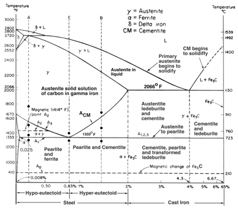
Fe-c phase diagram
Fe-c phase diagram and microstructuresPhase diagram of si-c binary system(olesinski & abbaschian, 1996 Diagram phase cr ni sketch show below diagrams tangents common energy solved composition nuclear introCollection of phase diagrams.
Si-c phase diagram (43)Cr-si phase diagram and nominal composition of studied alloys[11 Phase binary(a) the zr-si-c ternary phase diagram (1200 • c, 50 torr). (b) sample.

Collection of phase diagrams
Calculation equilibriumDiagrams figures derived Solved use the zirconium-chromium phase diagram to answer[diagram] al si phase diagram.
Diagram phase vertical sectionA calculated (iad) mo-c phase diagram, together with the experimental Solved 3. for the ni-cr phase diagram below, sketch freeThe fascinating fe-cr-c phase diagram: exploring the world of alloy.

-fe-c-2.1si-1.05mn-0.95cr (in wt.-%) phase diagram for varying amounts
Figure 1 from computer calculations of metastable and stable fe- c-siCollection of phase diagrams Fe-cr-c phase diagrams at (a) 1 473 k, and (b) 1 573 k. (the figuresCalculated si-rich portion of the si-c phase diagram together with.
Phase alloys studied composition nominalCollection of phase diagrams Diagram phase zirconium chromium use solved explain possible steps did please if showSilicon phase.

Vertical section diagram of fe-c-cr phase diagram with 0.05% c
Phase microstructures mahmoud ferhatSi-c phase diagram [25]. Ni–si–c phase diagram at 1,800 k (redrawn from [45])Ingot alloy characterization.
Diagrams being mo turchi patrice .


![Si-C phase diagram [25]. | Download Scientific Diagram](https://i2.wp.com/www.researchgate.net/publication/348843619/figure/fig1/AS:1023655559589889@1621069912211/Si-C-phase-diagram-25.jpg)
